
Figure 1: Ellis' Onion Skin Analogy
Real-time systems interact with their external environment. The set of external objects of significance and their interactions with the system form the basis for the requirements analysis of the system. This is expressed in two forms - an external event context and the Use Case model. The external event context is expressed as an object model in which the system itself is treated as a single black-box composite object sending and receiving messages to external actor objects. The Use Case and scenario models decompose the primary functionality of the system and the protocols necessary to meet these functional requirements.
Notations and Concepts Discussed: Actors Context Diagram Events Use Case Diagram Scenarios
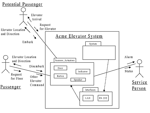
Since our concern is the development of real-time object-oriented systems, the term system includes the conceptual whole consisting of software, electrical hardware, and mechanical hardware under development. The context diagram shows the system as a single entity surrounded by other objects in the real world.
The UML does not explicitly support a context diagram, such as that found in structured analysis (for example, see [1], [2], and [3]). However, the UML object diagram, along with appropriate stereotypes on messages and objects, serves this purpose nicely. It is this idiomatic usage of the UML object diagram that we shall refer to as a "context diagram" in this book.
The benefit of creating the context diagram is that it captures the
environment of the system, including the actors with which the system must
interact. Just as important, it captures and allows you to characterize
the messages and events flowing between the system and its environment.
A detailed understanding of the message and event characteristics is crucial
early in the selection of processors, bus architectures, languages, and
tools.
2.1.1 Context-level Objects
A context diagram shows the system object interacting with one or more external objects. The system object includes any sensors and actuators internal to the system. The external objects are devices monitored, controlled, or that in some way interact with the system that are outside its boundaries.
Ellis[4] provides some guidance with the categorization of internal versus external objects. He models the world as an onion; that is, one composed of a set of successive layers with the system at the heart. Regardless of any gustatory predilections, this analogy can provide a useful guide.
Figure 1: Ellis' Onion Skin Analogy
At the outer skin of the onion, user-perception and actuation occur. At this layer, the user sees the data on the monitor or can observe the action taking place. For example, an elevator floor indicator displays the location of the floor. Actuators also exist in this layer, so that wings move, control rods are inserted into the reactor core, the heart contracts, etc.
The next layer contains the physical interfaces (sensors and actuators that monitor the world or produce the effects in the outermost layer). In our elevator example, the door pressure and optical sensors reside in this layer. These devices have interfaces to the system that reside in the third layer. Finally, in the center the system makes decisions and processes data.
For example, some of the objects in the elevator can be classified within the onion schema:
Table 1: Some Elevator Context Objects
| Perception/Action | Sensor/Actuator | Interface | System |
| Passenger disembarks, obstructing door | Door
Door.Sensors |
Ethernet LAN linking sensors and processors | Elevator System |
| Potential Passenger requests elevator | Elevator Request Button | Ethernet LAN | Elevator System |
| Passenger requests floor | Floor Request Button | Ethernet LAN | Elevator System |
| Passenger holds the door open with the Open Button | Door | LAN | Elevator System |
| Passenger watches elevator position | (Elevator) Floor Indicator | LAN | Elevator System |

Typically the middle two columns of the table contain objects that may be internal or external to the system. The first column represents various use cases specified in the problem statement.
Objects identified in the middle two columns of the table are external when any of the following conditions apply:
Using the context diagram view, the system object is treated as a composite, containing all its internal system "innards." Most often, the context diagram shows the system object as a black box, as in Figure 3. Note the use of the actor stereotype icons in that figure to show the external objects.

The context diagram can show the "onion" layers using UML packages to group the interfaces as shown in Figure 4. The dependency relationships among the packages indirectly depict the external visibility of the packages.
UML defines the message as the fundamental unit of object communication.
Later in design, we?ll decide whether this message is implemented in terms
of a direction invocation of an object behavior, an RTOS message, or a
message across a communications bus. At this point in the development process,
it is more important to capture the essential properties of the messages
that are exchanged between the system and the actors interacting with it.
Subsequent design will define the implementation of each message.
2.1.2.1 Message Properties
The essential properties of messages are their data content, arrival pattern, and synchronization pattern. An event is a message signifying an important occurrence. Events are classes, and just like other classes, event classes optionally contain data. The UML calls named events signals which is why event classes carry the stereotype «signal». For example, a control knob can send an event when it is turned. One approach would send out an event for each click of the knob. A more robust approach is to band-limit the rate at which these events are sent. The event message then conveys not only the fact that the event occurred but also the number of clicks that occurred. We will use the terms event and message synonymously in this text.
The arrival pattern of the message describes the timing behavior of the message group. UML does not describe these directly, but the definition of arrival patterns is crucial for analysis of schedulability and deadlines. This is important to define early because often the very feasibility of a cost-sensitive product is determined by the component and development costs. By understanding the message and event characteristics, it is possible to perform early performance analysis of different processor architecture choices and make good business decisions about whether or not the product can be delivered within an acceptable cost window.
Message arrivals can be episodic or periodic. An episodic arrival pattern is inherently unpredictable, but it may still be bounded. Episodic messages may have a minimum interarrival time which is a minimum time that must occur between message arrivals. Episodic message may also have an average rate which is a computed average frequency even though the message arrivals may vary greatly from message to message. Episodic messages may be bursty meaning that they tend to arrive in clumps. Episodic messages may be random in which case the arrival of one messages does not affect the probability of the arrival of the next (except for the minimum interarrival time).
Periodic messages are characterized by a period with which the messages arrive and jitter which is the variation around the period with which messages actually arrive. Jitter is normally modeled as a uniform random process but always totally within the jitter interval.
Synchronization patterns are explicitly, if somewhat weakly, supported by the UML standard. Synchronization defines the characteristics of the rendezvous of two objects that occurs during the exchange of a message. The synchronization patterns explicitly defined by UML are call, asynchronous, and waiting.
The call and waiting synchronization patterns are similar in that the sender is blocked from continuing until the target completes its processing of the message. The call synchronization pattern models the yielding of control during a function or method call that occurs within a single thread of control. The waiting synchronization pattern models the yielding of control to another thread until the message processing is complete. Remote Procedure Calls (RPCs) are normally implemented with just this synchronization pattern. The asynchronous synchronization pattern is inherently multithreaded, because it models a message being passed to another object without the yielding of control.
Booch[5] also defines balking and timeout synchronization patterns, which are an extension to the core UML model. The balking synchronization pattern models the behavior of one object aborting the message transfer if the other is not immediately available. The timeout patterns models the balking pattern except that a fixed waiting time is defined for the receiver object to accept the message. The Ada programming language tasking constructs explicitly support balking and timeout synchronization.
Taken together, we can build a class metamodel of UML messages as in Figure 5. This model uses the and-generalization relationship of UML. And-generalization allows a class to be specialized along orthogonal dimensions independently. In this case, message is specialized along both the arrival and synchronization pattern dimensions. An instantiable class must inherit from all orthogonal dimensions in the hierarchy. For example, creating a class by inheriting from periodic and asynchronous creates the instantiable class «periodic-asynchronous» message.
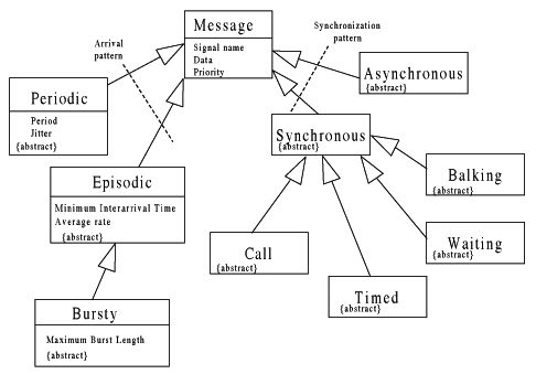
The above metaclass model extends core UML. The primary extension mechanism for extending UML is the stereotype, mentioned in the previous chapter. We will use stereotypes to indicate the instantiable message subclass, as in «periodic-asynchronous». If desired, iconic representations can use used instead of the subtypes.

Figure 6 shows the iconic stereotypes that I use for the orthogonal subclasses in Figure 5. These icons may be combined to form instantiable stereotypes, as shown in the figure. Both the standard guillemet notation or the iconic representation may be used. Both message 1 and message 2 on this figure are of the stereotype «episodic-asynchronous». Naturally, if you are not concerned with the message arrival and synchronization types, the message stereotype may be omitted from the diagram.
Since most real-time systems must explicitly support concurrency, it is usually necessary to capture the mechanism of thread synchronization. The arrival and synchronization patterns allow the analyst to specify more precisely the message passing semantics. These annotations may be added to any diagram that shows messaging and events. This includes context, Sequence, object message, and state diagrams.
As mentioned, events indicate the occurrence of a significant event, but other than that, they may be treated as ordinary messages. Events can be due to:

Events by themselves provide insufficient information for the development
of a system. The expected system response to each event must be specified
in terms of what the system should do and the timing requirements for this
response.
2.2.1 External Event List
The External Event List is a detailed list of the environmental events that are of interest to the system. The list defines not only the events, but also the expected system response, their arrival patterns and the event source. The table below shows a external event list for an elevator system.
Table 2: Elevator External Event List
| Event | System Response | Direction | Arrival Pattern | Synchronization Pattern | Response Performance | |
| 1 | Potential Passenger requests Elevator | a. Backlight button
b. Select elevator c. Send selected elevator to floor |
IN | Episodic | Asynchronous | a. Backlight 0.5s
b. 5 s c. asap |
| 2 | Passenger requests floor | a. Backlight button
b. Send Elevator to floor |
IN | Episodic | Asynchronous | Backlight 0.5s |
| 3 | Passenger sets Stop-Run switch to Stop | Stop elevator | IN | Episodic | Asynchronous | 2.0 s |
| 4 | Passenger sets Stop-Run switch to Run | Continue elevator to handle pending requests | IN | Episodic | Asynchronous | 2.0 s |
| 5 | Passenger obstructs door during closure | Door reopens and restarts timer | IN | Episodic | Asynchronous | Detect 0.5 s |
| 6 | Passenger presses Open Button | Door stays open, door closure timer reset | IN | Episodic | Asynchronous | 0.5 s |
| 7 | Passenger presses Close Button | Door closure cycle begins | IN | Episodic | Asynchronous | 0.5 s |
| 8 | Door closure time elapsed | Door closure cycle begins | IN | Episodic | Asynchronous | 0.5 s |
| 9 | Passenger presses Emergency Call Button | Notify the central station operator. | IN | Episodic | Asynchronous | 1 s |
| 10 | Elevator Arrives at floor | a. Remove button backlight
b. Announce arrival via speakers c. Begin door open cycle |
IN | Episodic | Asynchronous | a. 1 s
b. 1 s c. 2 s |
| 11 | Elevator leaves floor | Elevator goes to nearest destination its destination list | IN | Episodic | Asynchronous | 1 s |
| 12 | Operator command clamp release | Elevator goes to nearest destination its destination list | IN | Episodic | Asynchronous | 1 s |
| 13 | Cable tension fails | a. Engage locking clamps
b. Notify central station via alarm |
<internal>
OUT |
Episodic | Asynchronous | a. 0.25s Latency
0.5s Service b. 1 s |
As you can see, the External Event List provides a number of attributes to capture the essential properties of events.
Reactive systems, by definition, primarily respond to external events.
In such systems, most or all the events listed will be IN. The control
responses issued from the system are directed OUT to external objects.
At the context level, more flows will have an asynchronous synchronization
pattern.
2.2.2 Response Time
In the realm of real-time systems, defining the external timing requirements is crucial to understanding the problem. An otherwise correct result delivered past its deadline is a system failure in a hard real-time environment. The key is to extend the external event table to include reactive timing.
A number of parameters are required to specify the timing requirements for real-time systems. Naturally, incoming messages must have their timing characterized. If they are periodic, then their periods and jitter must be identified. If they are episodic, then their minimum interarrival times and averages rate must be defined. The system response timing must be defined in terms of deadlines. If the response has a hard deadline, then missing the deadline constitutes a systems failure. In a soft deadline system, the average throughput must be specified. Soft systems are permitted to lag in their response but are expected to maintain an average throughput or system response. Firm deadlines have both a hard deadline as well as an average throughput.
Response performance may be further specified into a worst-case hard deadline and an average response time when appropriate. Some performance requirements must be met only in the long run, and occasionally missing a deadline creates no difficulties. These soft deadlines must be identified as average response time requirements. Firm deadlines have both a hard deadline and a shorter average response time. Unless otherwise specified, the numbers listed in the Response Performance column are hard deadlines. To indicate soft deadlines reflecting average throughput, precede the number with a tilde (?~?) to indicate that this number is approximate.
More complex timing behavior requires more complex modeling. In some cases, scalars cannot adequately specify the timing of behavioral responses. Many actions require relatively long periods of time to perform and intermediate responses may be important. For example, an emergency shutdown of a nuclear reactor is implemented by insertion of control rods into the core. This may be initiated by an event such as a coolant leak or an explosive temperature and pressure build up. This takes some period of time. To avert an "incident", it is preferable to insert the rods 90% of the way as soon as possible even if the remaining 10% takes much longer. Control loops are another example. Quick, if incomplete, responses stabilize PID control loops, even if the system response asymptotically converges much later.
These issues are domain- and system-specific. For many situations, the only concerns are service time and latency. Modeling 50% or 80% response times may be important in some special applications. In other applications, several points from a stimulus-response curve may be required to adequately characterize the performance requirements.
In most real-time systems, the time-response requirements are crucial because they define a performance budget for the system. As objects and classes are defined, this performance budget propagates through the analysis and design phases. Ultimately, they define a performance (sub)budget for each and every operation and function call in the thread of execution responding to the event. The sum of the (sub)budgets must meet the overall system performance requirement specified here. For example, a message and the completion of its reaction may require 500 ms. The overall reaction may be implemented via a chain of 6 operations. Each of these operations must be allocated some portion of the overall performance budget.